


 Language
 English
 русский
 Español
 Português
 Deutsch
 عربى
عربى italiano
 Türk
Türk हिंदी
हिंदी Indonesia
 Tiếng Việt
If you need any help, please feel free to contact us

Aluminum Cable Trays for Solar Power Systems: Selection, Sizing and Installation
Content
- 1 Why Aluminum Cable Trays Dominate Solar Power Systems
- 2 Material Grades and Corrosion Management
- 3 Sizing and Load Calculation for Solar Cable Runs
- 4 Installation Best Practices for PV Projects
- 5 Matching Cable Trays to Photovoltaic Mounting Systems
- 6 Sourcing from a Full-Line Manufacturer
- 7 Frequently Asked Questions
A 50 MW ground-mounted solar plant can route more than 300 km of DC string cable through combiner boxes and inverter stations. If that cable is carried on a poorly specified tray, both the tray and the cable can fail long before the 30-year array design life is reached. Aluminum cable trays, specified from alloy grade to support spacing, keep a PV plant cable system serviceable for its full operating life.
Why Aluminum Cable Trays Dominate Solar Power Systems
Aluminum has a density of 2.7 g per cubic cm, roughly one-third of steel at 7.85 g per cubic cm. A 300 mm ladder tray weighs about 4.5 kg per meter in aluminum versus 13.5 kg per meter in hot-dip galvanized steel. That difference cuts shipping cost, reduces the load transmitted to PV mounting structures, and makes field handling safer for installation crews.
66%lighter than steel tray sections
25-40 yrsoutdoor service life in normal atmosphere
170 MPaminimum yield strength of 6063-T6
40%lower life-cycle cost vs galvanized steel in coastal air
Aluminum is also non-magnetic, which prevents eddy-current heating when the tray carries single-core AC conductors or high-frequency monitoring cables. Its surface oxide layer re-forms immediately after scratching, so a dent that would start rust on a galvanized tray does not compromise an aluminum tray. These properties make aluminum the material that best matches the outdoor, high-exposure operating profile of solar power systems.
Cable failure is a leading cause of downtime in solar plants. A 6063-T6 aluminum tray removes corrosion, UV degradation, and conductor overheating from that risk profile in one specification.
Material Grades and Corrosion Management
For a solar power system, 6063-T6 aluminum alloy is the standard starting specification because it balances structural strength, extrusion cost, and proven outdoor performance.
Alloy grade and temper
6063-T6 delivers a minimum yield strength in the range of 170 MPa, which is sufficient for ladder and trough trays on standard support spacings. Where the tray will carry heavy power cables or require longer unsupported spans, 6061-T6 with a minimum yield strength of roughly 240 MPa is the better choice. Any tray supplied for a PV project should carry a mill certificate confirming the alloy and temper.
Surface finish options
The alloy grade matters, but the finish determines how the tray behaves in a specific micro-climate. A bare mill finish is acceptable in indoor and arid installations. Coastal sites, high-humidity regions, and dusty industrial areas require an anodized, powder-coated, or PVDF-coated surface.
The complete aluminum alloy cable tray system from Jiangsu Youming Group Co., Ltd. covers ladder, trough, and punched tray profiles in multiple finishes, so a single procurement package can serve both the DC string cable and the communications cable route.
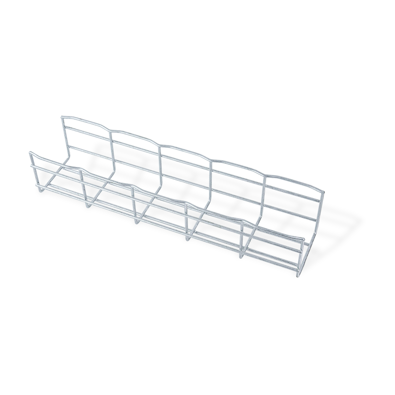 Custom Industrial Aluminum Alloy Cable Tray System ManufacturersJiangsu Youming Group Co., Ltd. is China Custom Industrial Aluminum Alloy Cable Tray System Manufacturers, Company, We Offer OEM/ODM Indu...View Product →
Aluminum 6063-T6
- One-third the weight of steel
- Self-healing oxide layer
- No painting or touch-up required
- Stable in UV and salt-laden air
Hot-dip galvanized steel
- Higher structural stiffness per kg
- Lower initial material cost
- Coating can be damaged in handling
- Higher life-cycle cost in coastal sites
The table below summarizes the finish options that should be evaluated for a solar project.
| Finish | Best suited for | Corrosion performance | Relative cost |
| Mill finish | Interior and arid sites | Moderate | 1.0x |
| Anodized AA15 | Coastal and high humidity | High | 1.3x |
| Powder coated | Industrial and dusty PV sites | High | 1.5x |
| PVDF coated | Marine and polluted zones | Very high | 1.9x |
Galvanic corrosion is the most common specification error in aluminum solar tray projects. Where aluminum contacts copper or bare galvanized steel in a damp environment without isolation, the aluminum corrodes. Specify stainless steel bolts, isolating washers, and separated support brackets at every mixed-metal junction.
Sizing and Load Calculation for Solar Cable Runs
Size a solar cable tray by cable fill, not by tray width alone: per NEC 392.22(B), the sum of cable cross-section areas must not exceed 50 percent of tray cross-sectional area, and every tray must withstand the installed cable load plus a 200 lb concentrated live load as defined in NEMA VE 1.
In practice, this means a 300 mm ladder tray carries about 32 to 42 DC cables sized 4 sq mm, depending on cable dressing and on the allowance for future circuits. Support spacing follows the load class, not the tray width. On a 1.5 m span, an aluminum ladder tray in load class C handles a uniform load of 150 kg per meter; increasing the span to 3.0 m can reduce the allowable load to around 40 kg per meter.
| Tray width (mm) | Typical DC cables | Uniform load rating | Recommended span (m) |
| 200 | Up to 28 | 60 kg/m | 1.5 |
| 300 | Up to 42 | 75 kg/m | 1.5 |
| 400 | Up to 56 | 100 kg/m | 2.0 |
| 600 | Up to 84 | 150 kg/m | 2.0 |
Structural weight is part of the load. The chart below compares the dead weight of a 300 mm ladder tray in the three materials most commonly quoted for solar projects.
Weight per linear meter, 300 mm ladder tray
Weights are typical catalog values for a 300 mm ladder tray without cover or fittings.
Design the cable run for the highest ambient temperature at the site. Aluminum derates at elevated temperature, and a span/300 deflection limit still applies when the tray is fully loaded in direct sun.
Installation Best Practices for PV Projects
Install aluminum cable trays in the sequence of support bracket mounting, tray assembly, expansion control, and cable dressing, and apply solar-specific rules for bend radius, UV exposure at tray entry points, and system bonding.
-
Fix supports at calculated spacing
Mount brackets at 1.5 to 2.0 m spacing on the PV structure. Use slotted adjustment plates so the tray line can be aligned after the structure tolerances have settled.
-
Assemble sections and splice plates
Connect tray sections with galvanized or stainless splice plates and torque fasteners to the manufacturer specification. Do not over-torque aluminum, which is softer than steel.
-
Install expansion couplers on long runs
Place expansion couplers at intervals of 20 to 25 m in unbroken tray runs to absorb thermal movement without buckling the splice plates.
-
Dress cables and control bend radius
Lay DC cables with a minimum bend radius of 5 times the cable outer diameter at every exit from the tray and at every combiner box entry.
-
Bond and ground the complete system
Bond the continuous tray system and connect it to the PV plant grounding network using listed clamps rated for aluminum-to-copper connections.
At 0.023 mm per meter per degree C, a 30 m unbroken aluminum tray run moves about 27 mm across a 40-degree C temperature swing. That movement has to be absorbed by expansion couplers, not by the splice plates.
Matching Cable Trays to Photovoltaic Mounting Systems
Solar cable trays perform correctly only when the tray support brackets are designed together with the PV mounting structure, because ground-mount and tracker frames are motion-critical systems that cannot accept rigid tray attachments.
Ground-mounted arrays
For fixed-tilt ground systems, tray brackets are usually clamped to the purlin or rail. The ground solar mounting structure determines the bracket height, so the tray layout should be confirmed before the steel is fabricated. For tracker systems, a service loop or flexible transition is required between the moving torque tube and the fixed cable path.
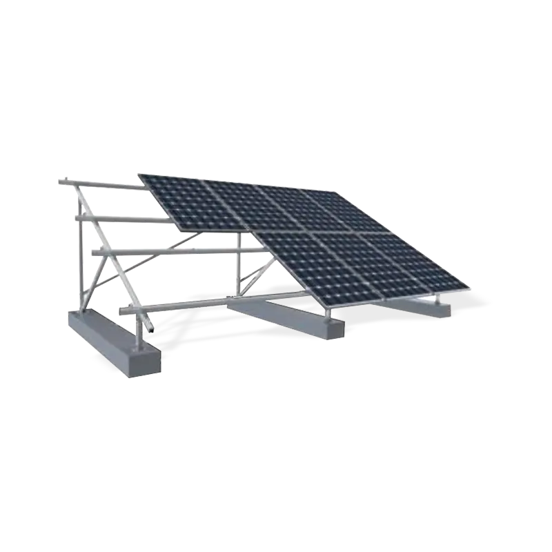 Wholesale Solar Ground Systems Steel Mounting Structure Manufacturers, OEM/ODM FJiangsu Youming Group Co., Ltd. is China Solar Ground Systems Steel Mounting Structure Manufacturers and Factory, Wholesale Solar Ground ...View Product →
Roof-mounted arrays
Roof projects benefit from aluminum trays because the low dead weight keeps additional roof loading to a minimum. Pair the trays with the photovoltaic mounting brackets from the same supplier so that bolt patterns and corrosion protection are consistent across the roof system.
Custom Outdoor Photovoltaic Stents ManufacturersJiangsu Youming Group Co., Ltd. is China Custom Outdoor Photovoltaic Stents Manufacturers, Company, We Offer OEM/ODM Outdoor Photovoltaic...View Product →
When tray brackets are bolted directly to a moving tracker, differential movement between the rotating torque tube and the fixed cable path can tear splice plates apart. Use flexible connectors or service loops at the boundary between moving and stationary zones.
Sourcing from a Full-Line Manufacturer
Jiangsu Youming Group Co., Ltd. has been producing cable tray systems since 2015 from its plant in Dongtai, Jiangsu Province. The company profile page documents a workshop area of more than 26,000 sq m and an annual cable tray capacity exceeding 30,000 tons. Its fully automated production lines handle coil slitting, roll forming, welding, riveting, laser cutting, and CNC turret punching, which means a 50 MW project can be quoted as one complete supply package rather than as a collection of parts.
Buyers who work with Youming also get engineering and testing capability for load calculations, custom profiles, and finish selection, which closes the gap between a tray drawing and a tray that installs without field rework.
30,000+ tons of annual capacity and 26,000 sq m of workshop space allow Youming to supply an entire PV project cable system, including fittings and supports, under one contract.
Frequently Asked Questions
Use these answers directly in a project specification or procurement inquiry.
What grade of aluminum is used for solar cable trays?
6063-T6 is the standard grade for extruded aluminum cable trays in solar power systems, with a minimum yield strength of about 170 MPa. Use 6061-T6 when the tray must span longer distances or carry heavier power cables.
Can aluminum cable trays be installed in coastal solar plants?
Yes. Specify anodized or PVDF-coated 6063-T6 aluminum and isolate every aluminum-to-copper or aluminum-to-steel connection with stainless steel hardware and isolating washers to prevent galvanic corrosion.
How do I calculate the cable tray size for a PV string?
Apply the NEC 392.22(B) fill rule: total cable cross-section area must stay at or below 50 percent of the tray cross-sectional area. Then verify the resulting cable load against the tray load class at the planned support spacing.
How often should expansion couplers be installed in aluminum trays?
Install expansion couplers every 20 to 25 m in continuous unbroken runs. Aluminum expands roughly twice as much as steel, so long, straight tray sections need a defined expansion point to avoid buckling.
Related Products
Recommended NEWS:
How to Choose Correctly? A Comparison and Selection Guide for Ladder Type vs. Trough Type Cable Trays
The Ultimate Guide to Trough Type Cable Trays: Selection, Installation, and Benefits
Punched Perforated Cable Tray vs. Other Cable Management: Core Advantages in Load Capacity, Heat Dissipation, and Installation Efficiency
Cable Tray Installation Tips: Steps to Ensure Safety and Efficiency
Aluminum Alloy Cable Tray Installation Guide: Step-by-Step Process
Recommended LINS:

Youming Group is a manufacturing group company mainly engaged in the research and development of new high-strength cable tray
Product
- Wire Type Cable Tray Series
- Punched Type Cable Tray Series
- Trough Type Cable Tray Series
- Cable Rack Ladder Series
- Ladder Type Cable Tray Series
- Marine Cable Ladder Tray
- Strut Channel Cable Tray Series
- Accessories
- Fiber Cable Tray/Optic Cable Tray
- Photovoltaic Stents
- Stainless Steel Cable Tray Series
- Aluminum Alloy Cable Tray System
Contact information
-
No.36, Taidong Industrial Zone Shiyan Town, Dongtai City, Jiangsu Province
