


 Language
 English
 русский
 Español
 Português
 Deutsch
 عربى
عربى italiano
 Türk
Türk हिंदी
हिंदी Indonesia
 Tiếng Việt
If you need any help, please feel free to contact us

How to Calculate Aluminum Cable Tray Load Capacity: The Engineer's Complete Guide
Content
An electrical contractor sizing a cable run for a three-story production hall has a 300 mm aluminum ladder tray on the drawing board: 34 power cables weighing 11.4 kg per meter, supports at 3 m intervals, and a deflection limit of L/100 in the specification. Before ordering material, the engineer has to answer one question. Will the tray carry that load at that span? The calculation decides the tray profile, the support layout, and the inspection sign-off.
69 GPa
Elastic modulus of structural aluminum
10 mm
Common deflection cap on a 3 m span
1.5x
Minimum safety factor for aluminum trays
3 m
Practical span ceiling for standard ladder trays
What Determines Aluminum Cable Tray Load Capacity
Aluminum cable tray load capacity is not a fixed number printed in a catalog. It is a calculated value that depends on tray geometry, aluminum alloy grade, support span, and the deflection limit set by the project specification.
Working definition: aluminum cable tray load capacity is the maximum uniform load, expressed in kilograms per meter (kg/m), that a tray run can carry at a given support spacing without exceeding the allowable deflection or the material stress limit.
Before any calculation begins, the tray geometry must be fixed. Width, side-rail depth, rung spacing, and bottom configuration all change the section properties that go into the equation. Jiangsu Youming Group Co., Ltd., which builds aluminum cable trays on automated roll-forming lines, documents these properties for each profile it ships. A guide to selecting the right aluminum alloy cable tray can lock in those dimensions before the load check starts.
| Variable | Effect on capacity | Typical range |
| Tray width | Wider trays spread cable weight across two side rails | 150-600 mm |
| Side-rail depth | Deeper rails increase bending stiffness | 75-150 mm |
| Support span | Capacity falls as span length rises | 1.5-3.0 m |
| Deflection limit | Tighter limits reduce the allowable load | L/100 or 10 mm |
Start With the Standard Beam Equation
Every aluminum tray load evaluation starts from the same simply supported beam equation for a uniformly loaded span. The equation is then rearranged to solve for the maximum uniform load the tray can carry before it reaches the allowable deflection.
deflection = 5wL4 / 384EI
Here, w is the combined cable and tray weight in kg/m, L is the distance between supports, E is the elastic modulus of aluminum (69,000 N/mm2 for common structural grades), and I is the moment of inertia of the tray cross-section, which the manufacturer provides. Because aluminum has about one-third the stiffness of steel, the same tray geometry deflects roughly three times more under the same load.
Aluminum tray
- Elastic modulus: 69 GPa
- Self-weight: roughly half of steel
- Corrosion: forms a protective oxide layer
- Thermal expansion: about double steel
Galvanized steel tray
- Elastic modulus: 200 GPa
- Self-weight: heavier, adds support loads
- Corrosion: needs coating protection
- Thermal expansion: lower, fewer concerns
At identical geometry, an aluminum tray deflects roughly three times more than a steel tray under the same load. Shorten the support span or specify a deeper side rail to bring deflection back inside the limit.
Six Steps for a Verified Load Calculation
A verified aluminum tray load calculation follows the same sequence on every project: collect cable data, add tray weight, fix the span, obtain the section property, run the checks, and compare against the limit.
- Inventory the cables. List every cable diameter and unit weight, then sum them into one value in kg/m. Add 10-15% for future circuits.
- Add tray self-weight. A 300 mm aluminum ladder tray adds 3-5 kg/m; trough types are heavier.
- Set the real span. Use as-built support spacing, not the 3 m from the layout drawing.
- Obtain the section property. The manufacturer must provide the moment of inertia for the exact profile. Aluminum alloy cable trays
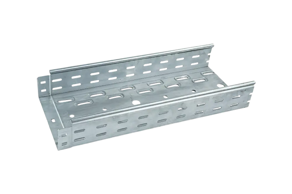
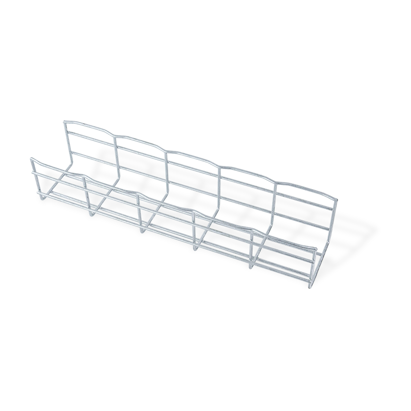 Custom Industrial Aluminum Alloy Cable Tray System ManufacturersJiangsu Youming Group Co., Ltd. is China Custom Industrial Aluminum Alloy Cable Tray System Manufacturers, Company, We Offer OEM/ODM Indu...View Product → from Youming are supplied with documented section data for this step.
 - Run both checks. Compute deflection from 5wL4 / 384EI and bending stress from M / S, where M = wL2 / 8. The lower result governs.
- Apply the safety factor. Divide the governing limit by at least 1.5 and confirm it exceeds the total weight from steps 1 and 2.
Safe uniform load, 300 mm aluminum ladder tray, deflection limit L/100 (indicative)
1.5 m
158 kg/m
2.0 m
118 kg/m
2.5 m
85 kg/m
3.0 m
64 kg/m
A 0.5 m change in span moves the allowable load by roughly 25-30%. Re-run the calculation every time the support layout changes, not once at the design stage. Where the tray profile is non-standard, a documented load capacity test across spans and deflections confirms what the equation predicts.
Compare the Result Against NEMA Load Classes
NEMA VE 1 and IEC 61537 translate tested tray capacity into load classes that save time during specification, but every class rating is valid only at the span used in the test.
| Class | Load rating (lb/ft) | Load rating (kg/m) | Typical application |
| A | 75 | 112 | Control and instrumentation cables |
| B | 100 | 149 | Mixed power and control circuits |
| C | 150 | 223 | Medium-voltage power feeders |
| D | 200 | 298 | Heavy industrial power runs |
A NEMA class rating is valid only at the tested span. If the as-built span is longer than the test span, the class rating cannot be applied without recalculation.
The metric conversions above are rounded. Apply a minimum 1.5 safety factor against the class rating before comparing it with the actual cable weight, and review the NEMA load class standards for strut cable trays, which follow the same rating logic.
Aluminum-Specific Factors That Change the Result
Three aluminum-specific properties change the calculation compared with steel: lower elastic modulus, higher thermal expansion, and softening at welded joints. Ignoring any of the three produces a result that is either unsafe or unnecessarily conservative.
- Lower stiffness. Aluminum E = 69 GPa against 200 GPa for steel; deflection usually governs before strength at typical cable loads.
- Thermal expansion. About double steel; long straight runs need expansion joints and anchor details that allow axial movement.
- Welded joints. Heat-affected zones reduce strength in 6061-T6; use mechanical connectors or 6063-T5 where field modifications are needed.
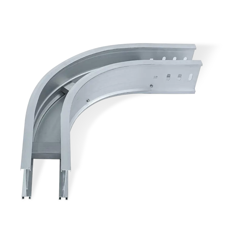
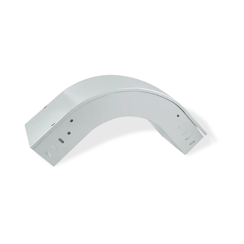
For heavy power runs where rung capacity matters, an aluminum cable ladder with sprayed plastic coating combines ladder-section load behavior with corrosion protection. Where the route changes direction, fittings must preserve the straight-section properties; aluminum alloy trunking elbows and tee accessories keep the cross-section continuous at transitions.
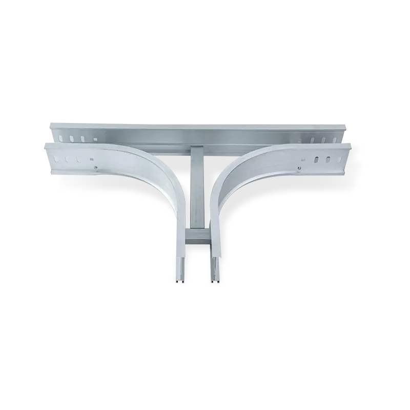
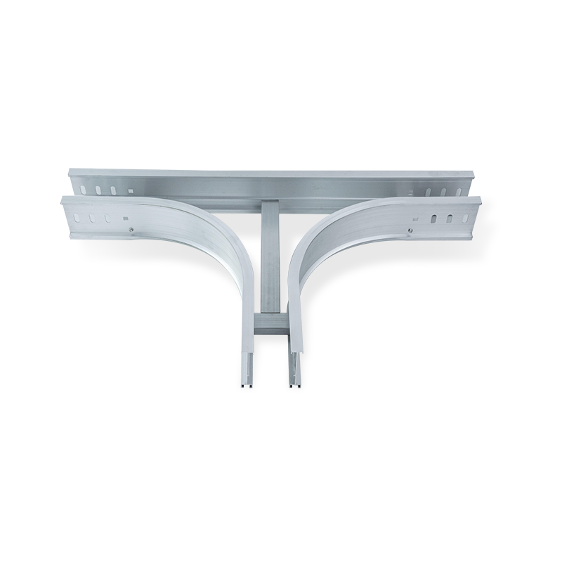 Custom Aluminum alloy cable trunking elbow tee accessories Suppliers, FactoryJiangsu Youming Group Co., Ltd. is China Custom OEM/ODM Aluminum alloy cable trunking elbow tee accessories Suppliers and Factory,Aluminu...View Product →
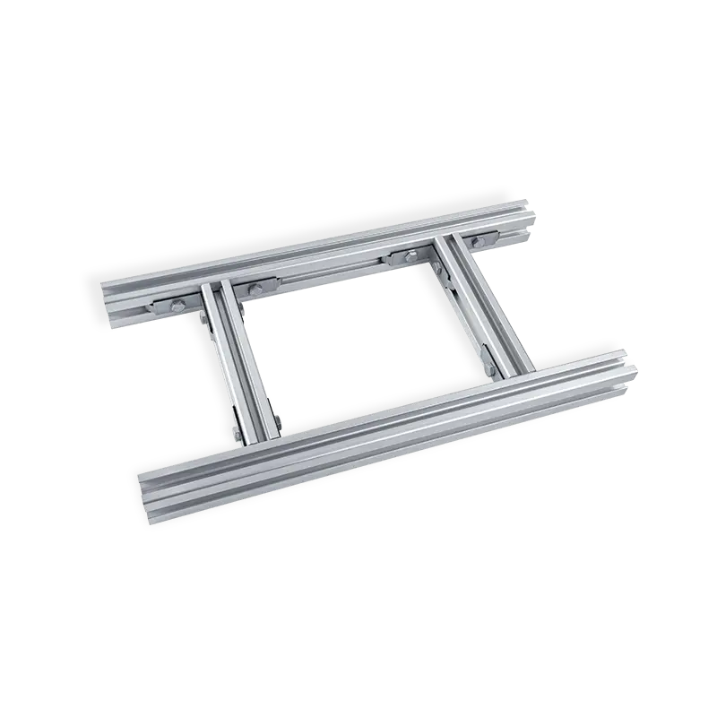
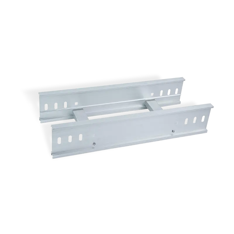 Custom Aluminum cable ladder Suppliers, FactoryJiangsu Youming Group Co., Ltd. is China Custom OEM/ODM Aluminum cable ladder Suppliers and Factory,Aluminum profile ladder cable tray, c...View Product →
The load calculation is only as reliable as the weakest element in the run. Fittings with thinner walls, bolted splices, or field-drilled holes can reduce effective capacity below the straight-tray value.
Frequently Asked Questions
Short answers to the questions engineers ask most often when specifying aluminum trays.
What is the maximum span for an aluminum cable tray?
For standard aluminum ladder trays, the practical maximum span is 3.0 m under uniform cable load, with 2.0-2.5 m preferred in most installations. Beyond 3.0 m, deflection control reduces the allowable load sharply, and heavy-duty profiles or intermediate supports are needed.
How much cable weight can a 300 mm aluminum tray carry?
At a 2.5 m span, a typical 300 mm aluminum ladder tray carries roughly 85 kg/m when the deflection limit is L/100. At 3.0 m, the same tray drops to about 64 kg/m. The exact figure depends on the side-rail profile, so the manufacturer's load table is the reference.
Does tray type change the calculation result?
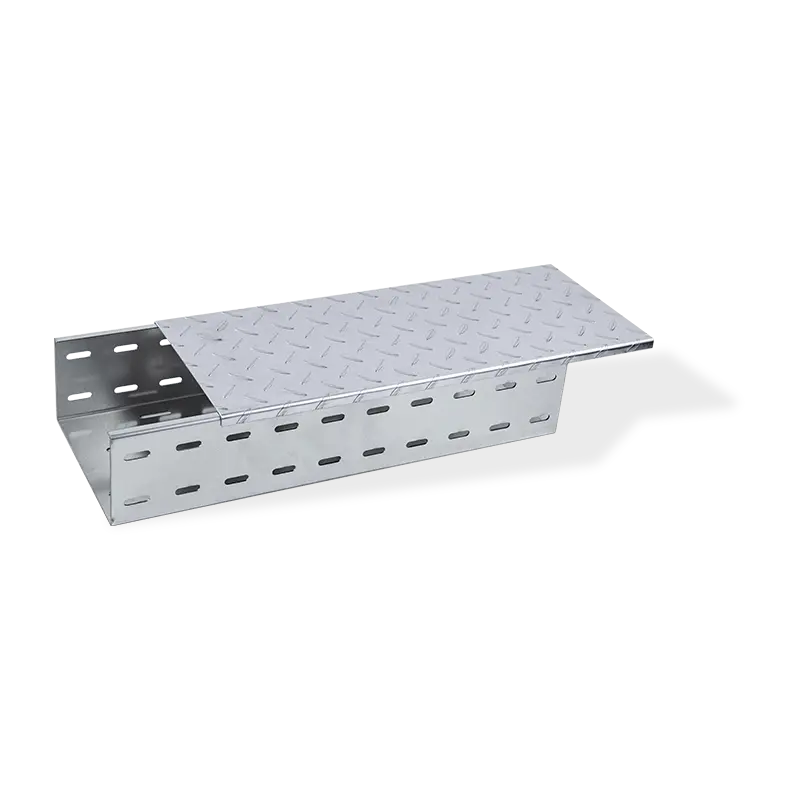
Yes. Ladder trays concentrate load on two side rails, trough trays add a solid or ventilated bottom that changes the moment of inertia and adds self-weight, and wire-mesh trays deform differently. Run the checks separately for each tray type on the same span.
Do I need a separate safety factor for aluminum?
Apply a minimum 1.5 safety factor for aluminum trays. Aluminum does not show the same yield plateau as mild steel, so stay below the 0.2% offset yield stress and check the heat-affected zone where field welding is used.
Related Products
Recommended NEWS:
The Critical Guide to Corrosion Resistance: Selecting the Right Ladder Rack Cable Tray for Specific Environments
The Ultimate Guide to Punched Type Perforated Cable Tray Series
The Ultimate Guide to Marine Cable Ladder Tray Systems
How to Choose Correctly? A Comparison and Selection Guide for Ladder Type vs. Trough Type Cable Trays
The Ultimate Guide to Trough Type Cable Trays: Selection, Installation, and Benefits
Recommended LINS:

Youming Group is a manufacturing group company mainly engaged in the research and development of new high-strength cable tray
Product
- Wire Type Cable Tray Series
- Punched Type Cable Tray Series
- Trough Type Cable Tray Series
- Cable Rack Ladder Series
- Ladder Type Cable Tray Series
- Marine Cable Ladder Tray
- Strut Channel Cable Tray Series
- Accessories
- Fiber Cable Tray/Optic Cable Tray
- Photovoltaic Stents
- Stainless Steel Cable Tray Series
- Aluminum Alloy Cable Tray System
Contact information
-
No.36, Taidong Industrial Zone Shiyan Town, Dongtai City, Jiangsu Province
